For Building an Sanguino you will need the Sanguino kit, you can bay it here :
Sanguino Kit
Mounting Instructions :
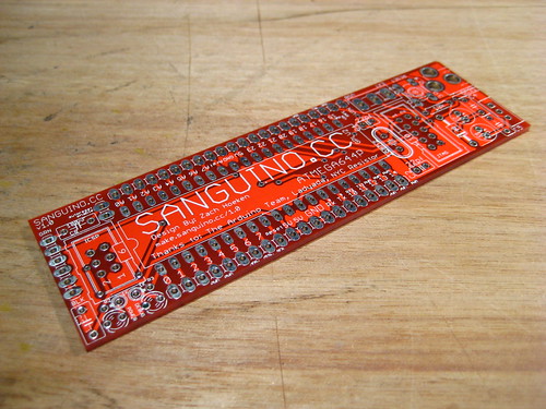
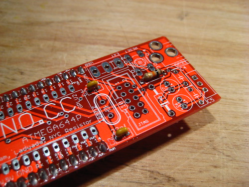
This is the Sanguino PCB
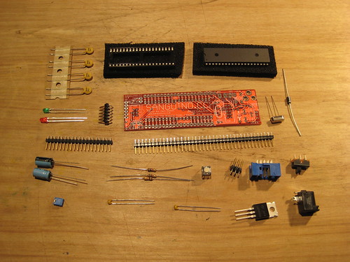
These Are The Components :
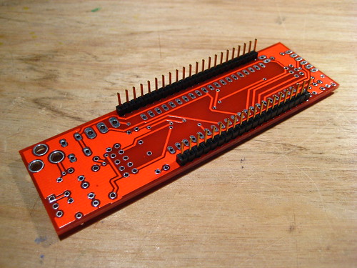
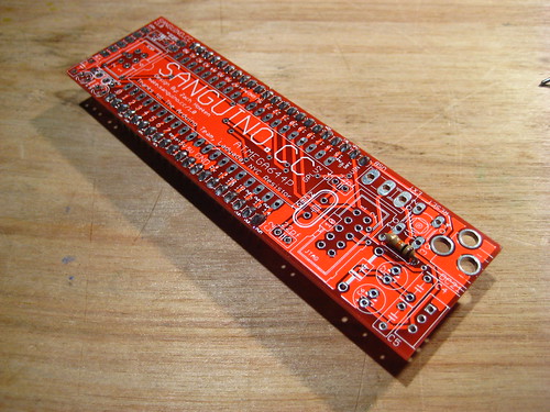
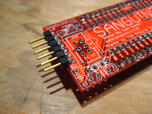
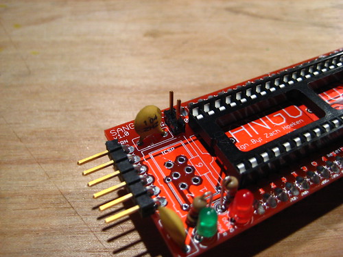
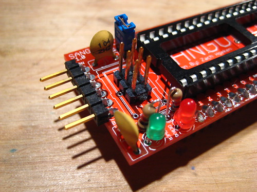
Solder Pin Headers
The pin headers are supposed to point down so you can insert the Sanguino into a breadboard. Make sure they are soldered in straight (perpendicular to the board.) An easy way to do this is to solder in one pin on each end of the row so that you can easily adjust them. Once they are straight, solder the rest of the pins.

Sanguino Kit
Mounting Instructions :
This is the Sanguino PCB
These Are The Components :
Solder Pin Headers
The pin headers are supposed to point down so you can insert the Sanguino into a breadboard. Make sure they are soldered in straight (perpendicular to the board.) An easy way to do this is to solder in one pin on each end of the row so that you can easily adjust them. Once they are straight, solder the rest of the pins.
10K resistor
Solder the resistor in any orientation. It is marked brown / black / orange.
22pF capacitors
These are the tiny yellow capacitors. They can be soldered in any orientation.
Serial Headers
Solder in the right-angle headers into the end of the board as shown.
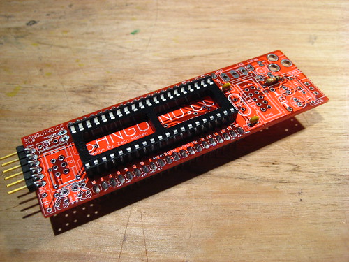
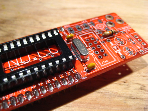
40-pin DIP Socket
Line up the DIP socket so that the dimple on one end lines up with the dimple on the silkscreen. Solder each pin in.
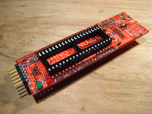
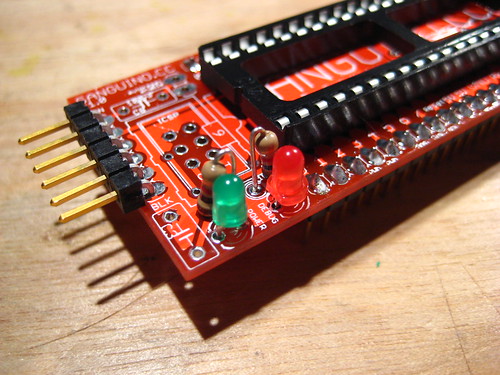
Red and Green LEDs
The LEDs need to be inserted in the proper orientation. The short leg of the LED goes into the flat side of the LED silkscreen.
16mhz Crystal
This is the crystal oscillator. It may be soldered in any orientation.
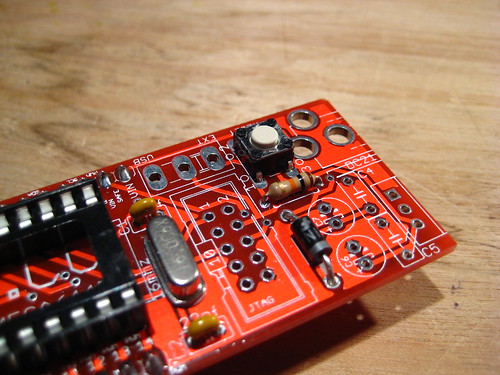
1N4001 Diode
This is the polarity protection diode. It needs to be soldered in in the proper orientation. There is a band on the diode. Line it up with the band on the silkscreen and solder it in.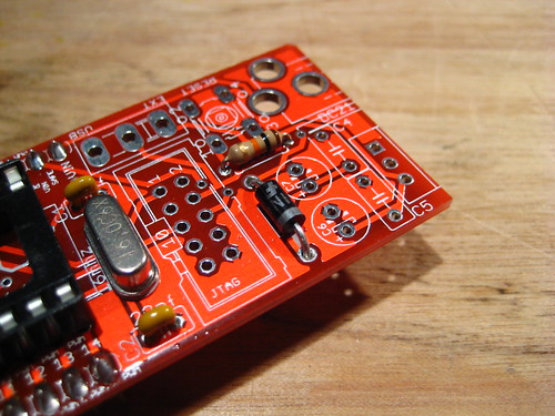
Reset Button
The button can only be inserted into the PCB in one orientation. Insert it and then solder it in.
1K Resistors
These are the resistors for the LEDs. They need to be mounted vertically, so bend one lead over and solder the resistors into the board.
100nF Ceramic Capacitors
The ceramic capacitors can be soldered in any orientation. There are 4 of them. Solder them all in.
Auto Reset Jumper Header
This is the jumper to enable/disable autoreset. Solder in a 2-pin header. It helps if its soldered in straight.
Put the jumper onto the header you just soldered it on. This enables the auto-reset functionality.
THIS IS IMPORTANT:
If you skip this step, you'll have to press reset every time before you upload your sketch.
THIS IS IMPORTANT:
If you skip this step, you'll have to press reset every time before you upload your sketch.
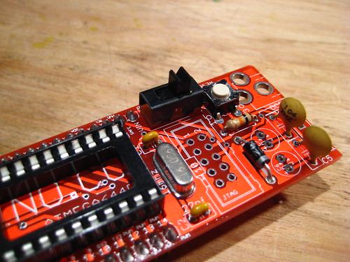
Power Selector
This switch allows you to choose between USB and External power. Solder it in any orientation.
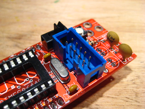
JTAG Header
This is the header to access the JTAG functionality. There is a notch in the IDC header that should line up with the silkscreen.
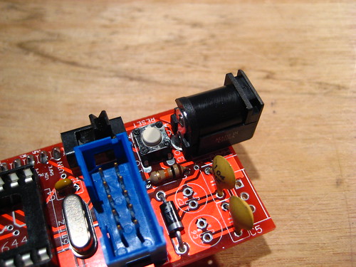
DC Power Jack
This is the jack for power input. It will take quite a bit of solder to solder it into place, so don't be shy.
ICSP Header
This is the header to directly flash the atmega644P chip. The pins can be soldered in any direction.
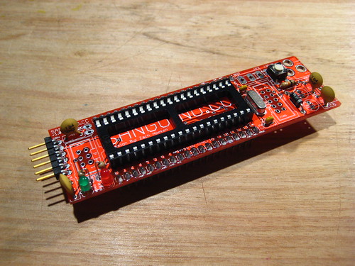
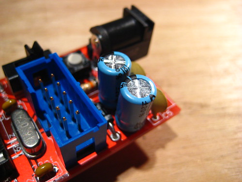
100uF Electrolytic Capacitors
These capacitors need to be soldered in the proper orientation. One side is marked as negative. The other pin is positive. Insert the positive leg in the side marked positive. It should look like that pictures.
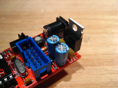
7805
This is the power regulator. Solder it so that the metal backing tab faces outwards.
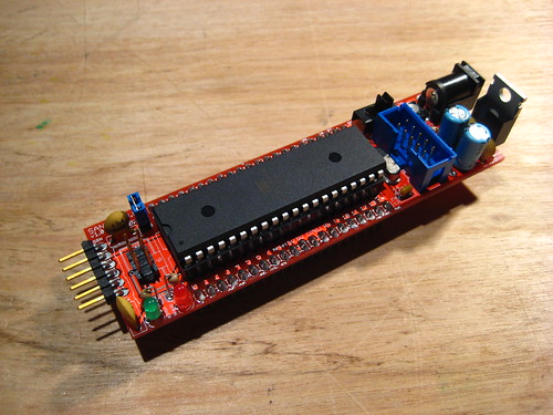
Insert atmega644P
Now is time to insert the atmega644P chip. Line the dimple up with the socket (and more importantly the silkscreen). Take care to not break / severely bend any legs as you insert it.
Now you can use it!


Tags:
Sanguino


Leave a comment