SAMP sends vehicle speed to a php script which a program on pc reads and echoes that data to COM port, so you can plug in this speed meter to a remote pc and monitor if your friend is speeding in samp.
Demonstrates the use of the analogWrite() function in fading an LED off and on. AnalogWrite uses pulse width modulation (PWM), turning a digital pin on and off very quickly, to create a fading effect.
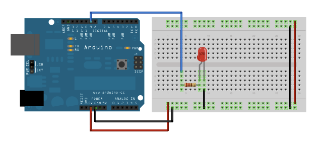
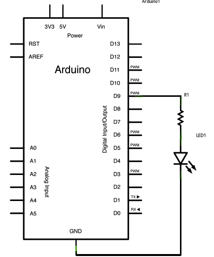
The Circuit
Connect the anode (the longer, positive leg) of your LED to digital output pin 9 on your Arduino through a 220-ohm resistor. Connect the cathode (the shorter, negative leg) directly to ground.
/*
Fade
This example shows how to fade an LED on pin 9
using the analogWrite() function.
This example code is in the public domain.
*/ int brightness =0;// how bright the LED is int fadeAmount =5;// how many points to fade the LED by
voidsetup(){ // declare pin 9 to be an output: pinMode(9,OUTPUT); }
voidloop(){ // set the brightness of pin 9: analogWrite(9, brightness);
// change the brightness for next time through the loop:
brightness = brightness + fadeAmount;
// reverse the direction of the fading at the ends of the fade: if(brightness ==0|| brightness ==255){
fadeAmount =-fadeAmount ; } // wait for 30 milliseconds to see the dimming effect delay(30); }
The Liquid Crystal Library allows you to control LCD displays that are compatible with the Hitachi HD44780 driver. There are many of them out there, and you can usually tell them by the 16-pin interface.
This example sketch shows how to use the autoscroll() and noAutoscroll() methods to move all the text on the display left or right.
autoscroll() moves all the text one space to the left each time a letter is added
noAutoscroll() turns scrolling off
This sketch prints the characters 0 to 9 with autoscroll off, then moves the cursor to the bottom right, turns autoscroll on, and prints them again.
Hardware Required
Arduino Board
LCD Screen (compatible with Hitachi HD44780 driver)
10k Potentiometer
breadboard
hook-up wire
Code
/*
LiquidCrystal Library - Autoscroll
Demonstrates the use a 16x2 LCD display. The LiquidCrystal
library works with all LCD displays that are compatible with the
Hitachi HD44780 driver. There are many of them out there, and you
can usually tell them by the 16-pin interface.
This sketch demonstrates the use of the autoscroll()
and noAutoscroll() functions to make new text scroll or not.
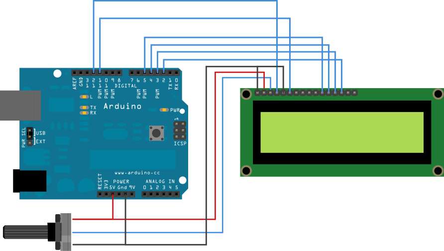
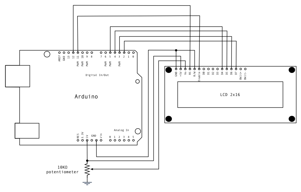
The circuit:
* LCD RS pin to digital pin 12
* LCD Enable pin to digital pin 11
* LCD D4 pin to digital pin 5
* LCD D5 pin to digital pin 4
* LCD D6 pin to digital pin 3
* LCD D7 pin to digital pin 2
* LCD R/W pin to ground
* 10K resistor:
* ends to +5V and ground
* wiper to LCD VO pin (pin 3)
Library originally added 18 Apr 2008
by David A. Mellis
library modified 5 Jul 2009
by Limor Fried (http://www.ladyada.net)
example added 9 Jul 2009
by Tom Igoe
modified 22 Nov 2010
by Tom Igoe
// initialize the library with the numbers of the interface pins
LiquidCrystal lcd(12,11,5,4,3,2);
voidsetup(){ // set up the LCD's number of columns and rows:
lcd.begin(16,2); }
voidloop(){ // set the cursor to (0,0):
lcd.setCursor(0,0); // print from 0 to 9: for(int thisChar =0; thisChar <10; thisChar++){
lcd.print(thisChar); delay(500); }
// set the cursor to (16,1):
lcd.setCursor(16,1); // set the display to automatically scroll:
lcd.autoscroll(); // print from 0 to 9: for(int thisChar =0; thisChar <10; thisChar++){
lcd.print(thisChar); delay(500); } // turn off automatic scrolling
lcd.noAutoscroll();
The Arduino Kitchen Timer is a simple timer based around a 10 bar LED Bar Graph, with a Piezo-Electric Buzzer. A line of 10 LED's could also be used, and each LED represents a segment of 5 mins. Once the Arduino is reset the user holds a pushbutton and the Bar Graph counts up in chunks of 5 mins, until the user lets go of the button. The timer then times 5 mins, and the last LED is turned off, etc until the timer is finished. The LED bar graph then shows a display, and a piezo buzzer sounds an alarm.
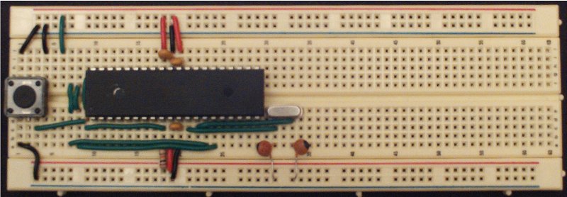
Put the bread board down vertically. Row 1 at top, blue rail left, red rail right.
Place the 644p into the bread board. Pin 1 into bread board hole 10D.
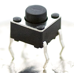
Place the momentary switch's pins into bread board 1D, 1F, 3D, and 3F.
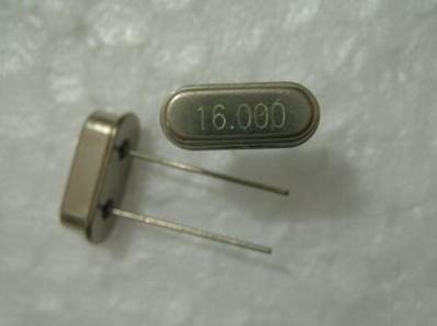
Place the crystal into rows 31E and 33E
Place a .1 uF cap from 9E to 9F. This is the reset on RTS cap. We'll be "building" a serial port on the left side, rows 4-9.
Place a .1 uF cap from 18I to 19I. Decouple AREF from AGND.
Place a .1 uF cap from 19I to 20I. Decouple AVCC from AGND. Yep, 19I, has 2 cap leads in it. It's a tight fit but can be done.
Place a .1 uF cap from 19C to 20C. Decouple VCC from GND.
Place 10K resistor from left VCC rail to 18A. This is the pull up resistor for RESET. Strictly speaking it isn't necessary. The 644p has an internal pull up resistor. But it's a little tiny one. Common practice seems to be to use a bigger one off chip.
Place a 22pf capacitor from left GND rail to 31A.
Place a 22pf capacitor from left GND rail to 33A.
** Wires **
1A to left GND. Part of the reset circuit from momentary switch to ground. Pressing switch connects reset to ground, resetting the chip. Also bridges GND from left GND rail to right GND rail through momentary switch.
1J to right GND rail.
3C to 9B. This will carry RESET from the RESET cap to the momentary switch.
4J to GND. Carry GND to serial port.
6J to VCC. Carry VCC to serial port.
7A to 23A, and 7E to 7G. Bring Rx to serial port.
8A to 24A, and 8E to 8G. Bring Tx to serial port.
9C to 18C. Bring RESET from chip to reset cap.
18J to right VCC. AREF.
19A to left VCC, chip VCC.
19J to right GND. AGND.
20A to left GND, chip GND.
20J to right VCC. AVCC.
21C to 31C. XTAL from chip to crystal.
22C to 33C. XTAL from chip to crystal.
Serial "port" is on the breadboard side B, column h, rows 4-9. FTDI USB cable black wire to row 4, green to row 9.
The FTDI cable has a female header. The short side of a male header is too short to fit into the breadboard. Easiest if you have them, is to use double length male headers to connect FTDI female connector to bread board hole. More likely you'll need to take two of the 6 pin male headers, and solder the short legs to each other. See the picture. Normally I use shrink fit tubing over bare wire after I solder to protect against shorts. But, there's no way to get them on in this case. So just solder REAL carefully.
To use the serial port, plug the FTDI cable into your computer and into the double sided male header you just created, which in turn is placed into the breadboard.
ICSP "port" is on side A, column B, rows 15-20.
Both the AVR MK-ISP2 and the USBTiny use a 6 pin ICSP female header, in a 2 row by 3 pin configuration. We need to make a cable going from a 2x3 male header to a 1x6 male header. We need to make the following cable using text mode "art":
Note, we are looking at the 2x3 header from the bottom. That is, at the pins.
To construct this cable, use either a crimping tool or solder. If you solder, split the ribbon cable back far enough that you can get in a bit of heatshrink without it shrinking when you solder the wire to the short side of the pin. After the wire is soldered, pull down the heat shrink to cover the joint, then shrink the tubing.
To use the ICSP port, plug your programmer into your computer, and the converter cable you created above into the 2x3 female connector of the programmer's cable. Green pin is pin 1, black is pin 6. Now plug the 1x6 end of the converter cable into the breadboard. Grey pin in hole 15B, Black in hole 20B.
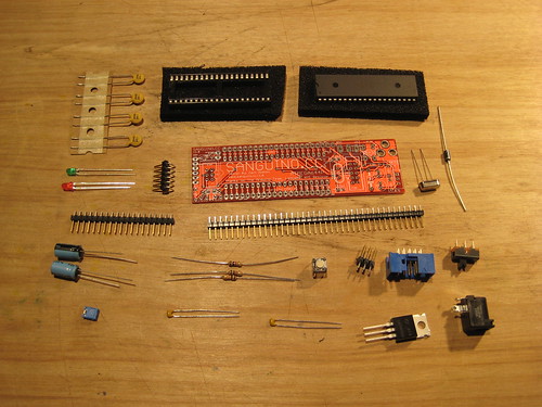
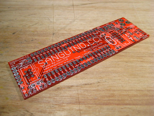
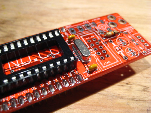
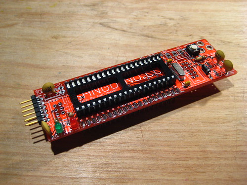
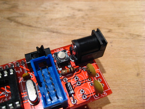
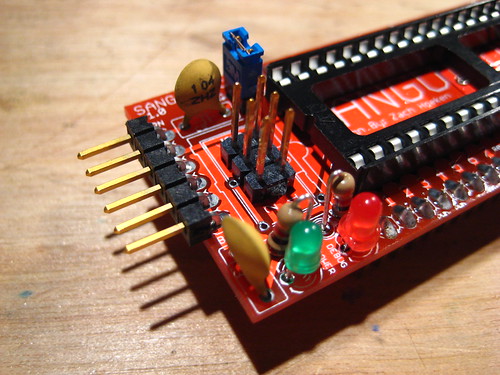
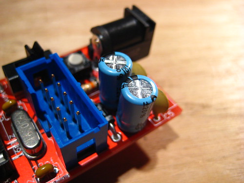
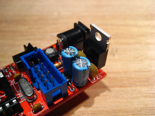
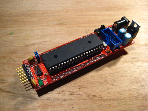
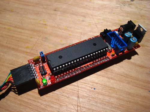
For Building an Sanguino you will need the Sanguino kit, you can bay it here : Sanguino Kit
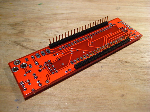
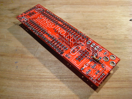
Mounting Instructions :
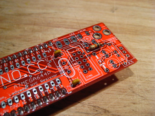
This is the Sanguino PCB
These Are The Components :
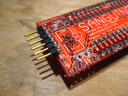
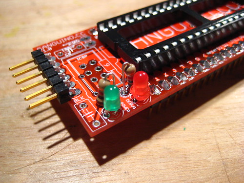
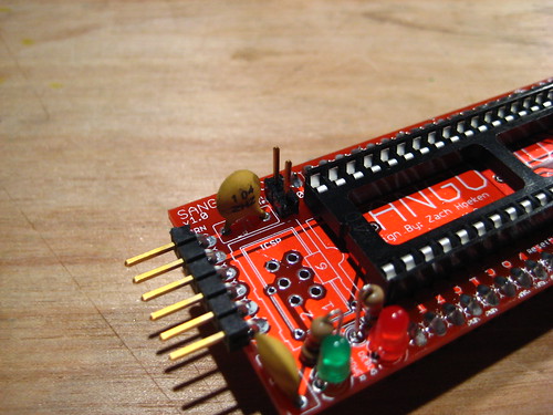
Solder Pin Headers
The pin headers are supposed to point down so you can insert the Sanguino into a breadboard. Make sure they are soldered in straight (perpendicular to the board.) An easy way to do this is to solder in one pin on each end of the row so that you can easily adjust them. Once they are straight, solder the rest of the pins.
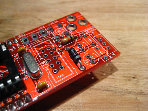
10K resistor
Solder the resistor in any orientation. It is marked brown / black / orange.
22pF capacitors
These are the tiny yellow capacitors. They can be soldered in any orientation.
Serial Headers
Solder in the right-angle headers into the end of the board as shown.
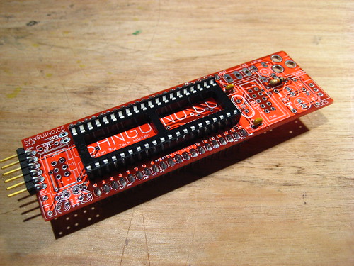
40-pin DIP Socket
Line up the DIP socket so that the dimple on one end lines up with the dimple on the silkscreen. Solder each pin in.
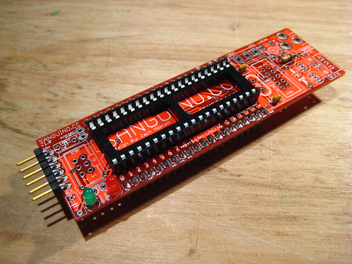
Red and Green LEDs
The LEDs need to be inserted in the proper orientation. The short leg of the LED goes into the flat side of the LED silkscreen.
16mhz Crystal
This is the crystal oscillator. It may be soldered in any orientation.
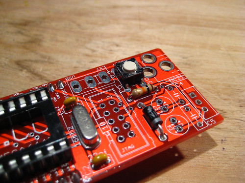
1N4001 Diode
This is the polarity protection diode. It needs to be soldered in in the proper orientation. There is a band on the diode. Line it up with the band on the silkscreen and solder it in.
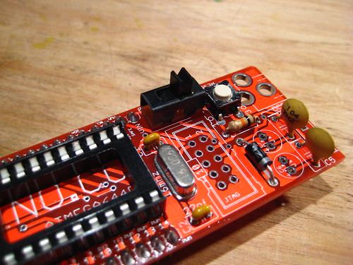
Reset Button
The button can only be inserted into the PCB in one orientation. Insert it and then solder it in.
1K Resistors
These are the resistors for the LEDs. They need to be mounted vertically, so bend one lead over and solder the resistors into the board.
100nF Ceramic Capacitors
The ceramic capacitors can be soldered in any orientation. There are 4 of them. Solder them all in.
Auto Reset Jumper Header
This is the jumper to enable/disable autoreset. Solder in a 2-pin header. It helps if its soldered in straight.
Put the jumper onto the header you just soldered it on. This enables the auto-reset functionality. THIS IS IMPORTANT:
If you skip this step, you'll have to press reset every time before you upload your sketch.
Power Selector
This switch allows you to choose between USB and External power. Solder it in any orientation.
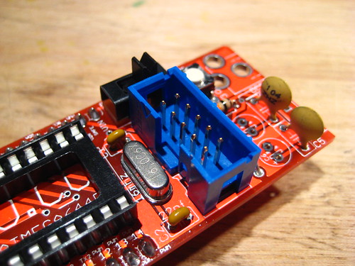
JTAG Header
This is the header to access the JTAG functionality. There is a notch in the IDC header that should line up with the silkscreen.
DC Power Jack
This is the jack for power input. It will take quite a bit of solder to solder it into place, so don't be shy.
ICSP Header
This is the header to directly flash the atmega644P chip. The pins can be soldered in any direction.
100uF Electrolytic Capacitors
These capacitors need to be soldered in the proper orientation. One side is marked as negative. The other pin is positive. Insert the positive leg in the side marked positive. It should look like that pictures.
7805
This is the power regulator. Solder it so that the metal backing tab faces outwards.
Insert atmega644P
Now is time to insert the atmega644P chip. Line the dimple up with the socket (and more importantly the silkscreen). Take care to not break / severely bend any legs as you insert it.
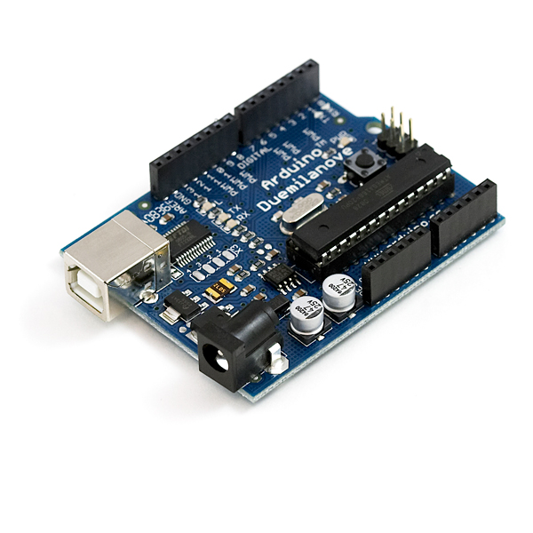
Sanguino is an open source hardware like Arduino( infect it use the Arduino Ide)but it has some additional I/O pins for example it has 32 total general purpose I/O pins, 64K flash memory, 2K EEPROM etc.. the Main Processor is atmega644P and obviously its 100% open source.
A beautiful project by [Leigh Davis]. It is a brilliant proof of how Arduino fits into virtually any sphere of thought and is the shortest path for a creator realizing his idea in reality.
He writes:
I began the first few days by developing a stand alone application build in MaxMSP that understands the notes that a play on my (recently purchased second-hand) flute. I set the range from low C right up to the 3rd octave D. Each note of the chromatic scale triggers a bang, which is coloured uniquely to the other notes bang messages.
The bang message then sets the corresponding color to the display screen on the application. Which will in turn send a signal to the arduino to dispense the corresponding oil color on water according to the different notes. (Something like a physical Milkdrop!)He further plans to control different LEDs, motors and the likes using the Rayne application.
Hello
Today i've re build my old project.
Here is the schematic :
You can use any type of ir receiver with your arduino, i've use an old ir receiver form my brooked tv.
after Wiring up all upload this code into your Arduino:
/* 5 Channel ir remote control
Created by Asghar Furqan
A fully open-sourse program!
---------------------------------------------------------
circuit:
ir module connected to pin 2(Digital)
led 1-2-3-4-5 connected to pin 3-4-5-6-7
*/
#include
int RECV_PIN = 2;
int led1 = 7;
int led2 = 3;
int led3 = 4;
int led4 = 5;
int led5 = 6;
if (irrecv.decode(&results)) {
Serial.println(results.value, DEC);
if(results.value == 16705559) //if you want to configure with your remote controll change the results.value
digitalWrite(led1, HIGH); // set the LED on
if (irrecv.decode(&results)) {
Serial.println(results.value, DEC);
if(results.value == 16656599)
digitalWrite(led1, LOW); // set the LED off
irrecv.resume(); // Receive the next value
if(results.value == 16672919)
digitalWrite(led2, HIGH); // set the LED on
if(results.value == 16697399)
digitalWrite(led2, LOW); // set the LED off
irrecv.resume(); // Receive the next value
if(results.value == 16689239)
digitalWrite(led3, HIGH); // set the LED on
if(results.value == 16664759)
digitalWrite(led3, LOW); // set the LED off
irrecv.resume(); // Receive the next value
if(results.value == 16668839)
digitalWrite(led4, HIGH); // set the LED on
if(results.value == 16676999)
digitalWrite(led4, LOW); // set the LED off
irrecv.resume(); // Receive the next value
if(results.value == 16674959)
digitalWrite(led5, HIGH); // set the LED on
if(results.value == 16650479)
digitalWrite(led5, LOW); // set the LED off
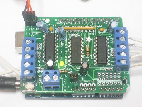
Arduino is a great starting point for electronics, and with a motor shield it can also be a nice tidy platform for robotics and mechatronics. Here is a design for a full-featured motor shield that will be able to power many simple to medium-complexity projects.
2 connections for 5V 'hobby' servos connected to the Arduino's high-resolution dedicated timer - no jitter!
Up to 4 bi-directional DC motors with individual 8-bit speed selection (so, about 0.5% resolution)
Up to 2 stepper motors (unipolar or bipolar) with single coil, double coil, interleaved or micro-stepping.
4 H-Bridges: L293D chipset provides 0.6A per bridge (1.2A peak) with thermal shutdown protection, 4.5V to 36V
Pull down resistors keep motors disabled during power-up
Big terminal block connectors to easily hook up wires (10-22AWG) and power
Arduino reset button brought up top
2-pin terminal block to connect external power, for seperate logic/motor supplies
Tested compatible with Mega, Diecimila, & Duemilanove
How to use
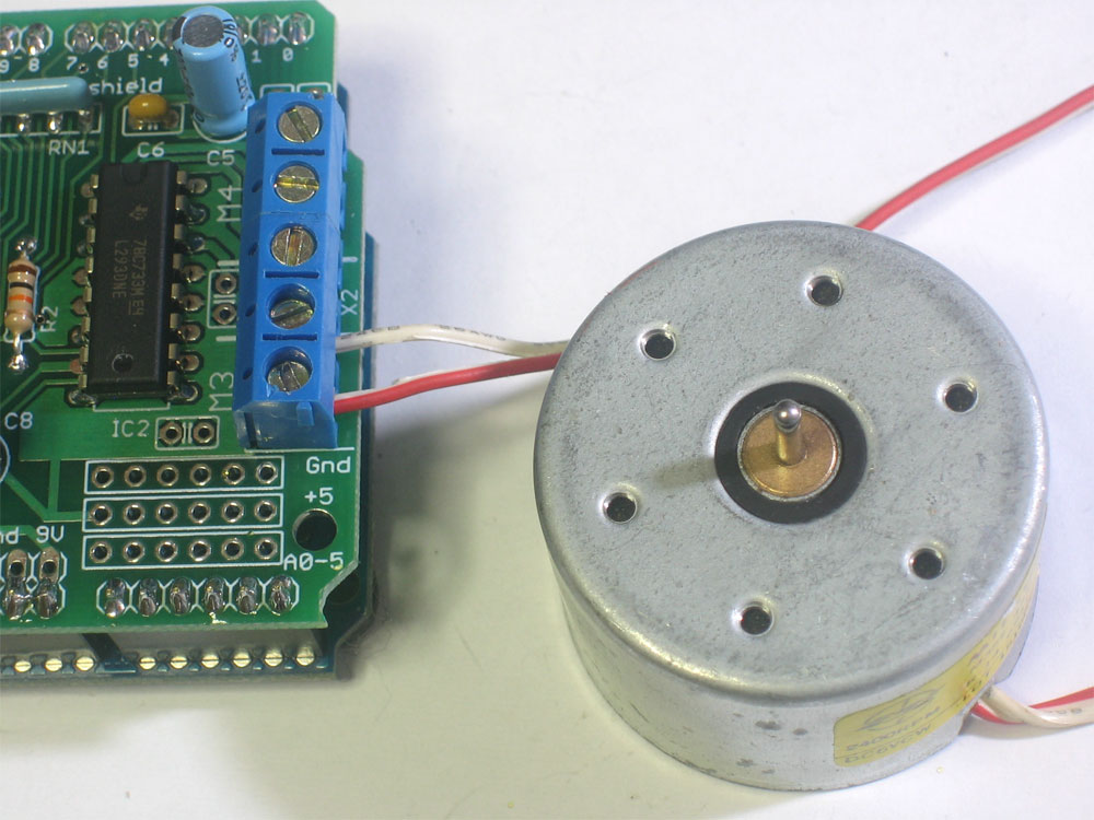
DC motors
DC motors are used for all sort of robotic projects. The motor shield can drive up to 4 DC motors bi-directionally. That means they can be driven forwards and backwards. The speed can also be varied at 0.5% increments using the high-quality built in PWM. This means the speed is very smooth and won't vary!
Note that the H-bridge chip is not really meant for driving loads over 0.6A or that peak over 1.2A so this is for small motors. Check the datasheet for information about the motor to verify its OK.
To connect a motor, simply solder two wires to the terminals and then connect them to either the M1, M2, M3, or M4. Then follow these steps in your sketch
Make sure you include
Create the AF_DCMotor object with AF_DCMotor(motor#, frequency), to setup the motor H-bridge and latches. The constructor takes two arguments.
The first is which port the motor is connected to, 1, 2, 3 or 4. frequency is how fast the speed controlling signal is.
For motors 1 and 2 you can choose MOTOR12_64KHZ, MOTOR12_8KHZ, MOTOR12_2KHZ, or MOTOR12_1KHZ. A high speed like 64KHz wont be audible but a low speed like 1KHz will use less power. Motors 3 & 4 are only possible to run at 1KHz and will ignore any setting given
Then you can set the speed of the motor using setSpeed(speed) where the speed ranges from 0 (stopped) to 255 (full speed). You can set the speed whenever you want.
To run the motor, call run(direction) where direction is FORWARD, BACKWARD or RELEASE. Of course, the Arduino doesn't actually know if the motor is 'forward' or 'backward', so if you want to change which way it thinks is forward, simply swap the two wires from the motor to the shield.
Code
#include
AF_DCMotor motor(2, MOTOR12_64KHZ); // create motor #2, 64KHz pwm
voidsetup() {
Serial.begin(9600); // set up Serial library at 9600 bpsSerial.println("Motor test!");
motor.setSpeed(200); // set the speed to 200/255
}
voidloop() {
Serial.print("tick");
motor.run(FORWARD); // turn it on going forwarddelay(1000);
Serial.print("tock");
motor.run(BACKWARD); // the other waydelay(1000);
Serial.print("tack");
motor.run(RELEASE); // stoppeddelay(1000);
}

 <-- This is computer softwere.